For an uncontrolled three-phase bridge rectifier, six diodes are used, and the circuit again has a pulse number of six. For this reason, it is also commonly referred to as a six-pulse bridge. The B6 circuit can be seen simplified as a series connection of two three-pulse center circuits.
For low-power applications, double diodes in series, with the anode of the first diode connected to the cathode of the second, are manufactured as a single component for this purpose. Some commercially available double diodes have all four terminals available so the user can configure them for single-phase split supply use, half a bridge, or three-phase rectifier.
For higher-power applications, a single discrete device is usually used for each of the six arms of the bridge. For the very highest powers, each arm of the bridge may consist of tens or hundreds of separate devices in parallel (where very high current is needed, for example in aluminium smelting) or in series (where very high voltages are needed, for example in high-voltage direct current power transmission).
The pulsating DC voltage results from the differences of the instantaneous positive and negative phase voltages

phase-shifted by 30°:

The ideal, no-load average output voltage

of the B6 circuit results from the integral under the graph of a DC voltage pulse with the period duration of
 (from 60° to 120°) with the peak value
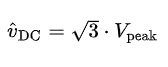 :
:

If the three-phase bridge rectifier is operated symmetrically (as positive and negative supply voltage), the center point of the rectifier on the output side (or the so-called isolated reference potential) opposite the center point of the transformer (or the neutral conductor) has a potential difference in the form of a triangular common-mode voltage. For this reason, these two centers must never be connected to each other, otherwise short-circuit currents would flow. The ground of the three-phase bridge rectifier in symmetrical operation is thus decoupled from the neutral conductor or the earth of the mains voltage. Powered by a transformer, earthing of the center point of the bridge is possible, provided that the secondary winding of the transformer is electrically isolated from the mains voltage and the star point of the secondary winding is not on earth. In this case, however, (negligible) leakage currents are flowing over the transformer windings.
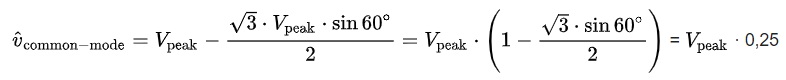
The common-mode voltage is formed out of the respective average values of the differences between the positive and negative phase voltages, which form the pulsating DC voltage. The peak value of the delta voltage
amounts 1/4 of the peak value of the phase input voltage

and is calculated with
minus half o the DC voltage at 60° of the period:
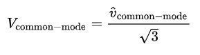
The RMS value of the common-mode voltage is calculated from the form factor for triangular oscillations:
If the circuit is operated asymmetrically (as a simple supply voltage with just one positive pole), both the positive and negative poles (or the isolated reference potential) are pulsating opposite the center (or the ground) of the input voltage analogously to the positive and negative waveforms of the phase voltages. However, the differences in the phase voltages result in the six-pulse DC voltage (over the duration of a period). The strict separation of the transformer center from the negative pole (otherwise short-circuit currents will flow) or a possible grounding of the negative pole when powered by an isolating transformer apply correspondingly to the symmetrical operation.
